The USB Type-C specification defines connectors and cables that allow users to insert their devices and cables without worrying about orientation (reversible). Both ends of the cable can use Type-C plugs, and if needed, one end can use legacy USB plugs (such as micro-A, Type-A, or Type-B). To support higher bandwidth applications, the USB Type-C specification incorporates multiple USB 3.1 pairs within the connector.
Notably absent from the USB Type-C socket are the ID pins found on previous Type-A and Type-B connectors. Instead, Type-C employs a different approach using the Configuration Channel (CC) pin to determine whether a device functions as a host or a peripheral. The CC pin performs the same role as the ID pin previously did; indicating whether the device functions as a host, a peripheral, or both. The CC pins also detect whether a connection is established or disconnected. Additionally, several other pins are present on Type-C that were not required for USB 2.0 implementation.
Type-C Pins

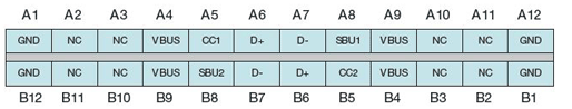
The diagram below shows the pin assignment for a receptacle supporting a full-function Type-C cable. A full-function cable supports both USB 2.0 and USB 3.1.
Type-C Pins
When transitioning from USB 2.0 OTG products to Type-C products, USB 3.1 signals are not required. These signals should remain unconnected (electrically isolated) on the PCB. The diagram below shows the unconnected USB 3.1 contacts in a Type-C receptacle.
Unconnected USB 3.1 Contacts in Type-C
The pin diagram shows two sets of D+ and D- contacts. These two sets do not indicate two separate USB 2.0 paths. In fact, a Type-C cable has only one wire for D+ and only one wire for D-. The purpose of these two sets of D/D- contacts is to support the “reversible” feature.
The product should connect both D+ pins to its PCB and both D– pins to its PCB. When the user connects these pins together on the PCB, stubs will inevitably be created. Therefore, note that stub length must not exceed 2.5mm. Otherwise, signal integrity issues may be observed on the USB 2.0 interface.
The ID pin is notably absent from the USB Type-C receptacle. Type-C determines host or peripheral functionality differently. The device’s role as host or peripheral must be detected by monitoring the Configuration Channel (CC) pins (CC1/CC2). This requires switching between the pull-up resistor and pull-down resistor at specific time intervals. After a defined debounce period, the device assumes the role of host or peripheral based on the voltage level measured on the CC pins.
- High-Performance Waterproof Solar Connectors
- Durable IP68 Waterproof Solar Connectors for Outdoor Use
- High-Quality Tinned Copper Material for Durability
- High-Quality Tinned Copper Material for Long Service Life
- Y Branch Parallel Solar Connector for Enhanced Power
- 10AWG Tinned Copper Solar Battery Cables
- NEMA 5-15P to Powercon Extension Cable Overview
- Dual Port USB 3.0 Adapter for Optimal Speed
- 4-Pin XLR Connector: Reliable Audio Transmission
- 4mm Banana to 2mm Pin Connector: Your Audio Solution
- 12GB/s Mini SAS to U.2 NVMe Cable for Fast Data Transfer
- CAB-STK-E Stacking Cable: 40Gbps Performance
- High-Performance CAB-STK-E Stacking Cable Explained
- Best 10M OS2 LC to LC Fiber Patch Cable for Data Centers
- Mini SAS HD Cable: Boost Data Transfer at 12 Gbps
- Multi Rate SFP+: Enhance Your Network Speed
- Best 6.35mm to MIDI Din Cable for Clear Sound
- 15 Pin SATA Power Splitter: Solutions for Your Device Needs
- 9-Pin S-Video Cable: Enhance Your Viewing Experience
- USB 9-Pin to Standard USB 2.0 Adapter: Easy Connection
- 3 Pin to 4 Pin Fan Adapter: Optimize Your PC Cooling
- S-Video to RCA Cable: High-Definition Connections Made Easy
- 6.35mm TS Extension Cable: High-Quality Sound Solution
- BlackBerry Curve 9360: Key Features and Specs


Leave a comment