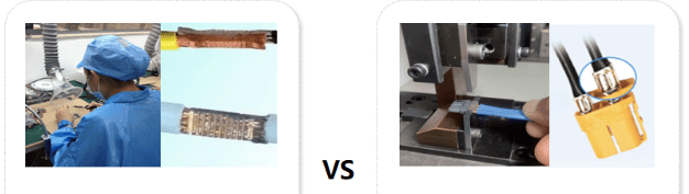
To distinguish between welding and riveting processes for connectors, we can start from multiple aspects such as process principles, appearance characteristics, connection strength, and application scenarios. The detailed comparison is as follows:
1. Process Principles and Operation Methods
- Welding Process: It heats (e.g., with a soldering iron or reflow soldering equipment) to melt the solder (such as tin-lead alloy), filling the gap between the connector pins and the circuit board pads. After cooling, a metallic bond is formed to achieve electrical connection. This process requires tools like soldering irons, soldering stations, reflow ovens, or wave soldering equipment, and uses solder (e.g., solder wire or paste) as a filler material.
- Riveting Process: It applies mechanical pressure to the connector pins (or terminals) through rivets or riveting tools, causing plastic deformation to squeeze and fix the connector with the base material (such as the circuit board or metal shell), forming a mechanical connection. Tools like riveting machines, crimping pliers, or manual rivet guns are used, and no filler material is needed, relying solely on mechanical deformation for fixation.
2. Appearance Features and Structural Details
- Appearance of Connection Points: Welded joints have smooth surfaces with possible solder accumulation or fusion marks, showing a metallic luster (e.g., silver-white), and the junction between pins and pads is obviously wrapped by solder. For riveting, deformation marks of rivets or terminals can be seen, such as flattened crimping areas or raised rivet heads. The edges of pins or terminals may have wrinkles or deformations from extrusion, with no solder luster on the surface.
- Shape of Pins/Terminals: Welded pins are usually through-hole (DIP) or surface-mount (SMT), and after welding, the pins are basically flush with the circuit board or slightly protruding, without obvious mechanical deformation. Riveted terminals (such as crimp terminals) may be tubular or U-shaped, and after riveting, the terminals are crimped to tightly wrap the wires or circuit board holes, with pins possibly deformed (e.g., bent or flattened) due to extrusion.
3. Connection Strength and Reliability
- Mechanical Strength: The mechanical strength of welds depends on the bonding force between the solder and the metal surface, with moderate resistance to tension and vibration. Long-term vibration may cause solder joints to crack. Riveting forms a rigid connection through mechanical deformation, with strong resistance to tension and vibration, suitable for scenarios requiring frequent plugging or harsh environments (such as industrial equipment).
- Electrical Connection Stability: Welds have excellent conductivity and low contact resistance, suitable for high-frequency signals or large current transmission, but high temperatures or oxidation may affect their service life. Riveting’s electrical connection relies on the close contact of metal surfaces. If the contact surface is oxidized or the deformation is insufficient, the contact resistance may increase, with slightly lower stability than welding.
- Temperature Resistance: The temperature resistance of welds depends on the solder type (e.g., lead-free solder can withstand about 217°C), and they may soften or melt in high-temperature environments. Riveted parts are directly 挤压 connected by metals, with better temperature resistance, suitable for high-temperature scenarios (such as automotive electronics or industrial control).
4. Application Scenarios and Typical Cases
- Common Application Fields: Welding is widely used in consumer electronics (e.g., mobile phone motherboards, computer connectors), household appliances, and precision circuit boards (e.g., HDMI, USB connectors), suitable for scenarios requiring high-density wiring and miniaturization. Riveting is applied in automotive electronics (e.g., wiring harness terminal crimping), industrial equipment (e.g., power distribution cabinet connectors), and aerospace (high-reliability mechanical connections), suitable for large current and high-vibration environments.
- Typical Connector Types: Welding is used for SMT patch connectors (e.g., FPC connectors), DIP pin connectors (e.g., pin headers), and welded terminal blocks (e.g., PCB terminal posts). Riveting is used for crimp terminals (e.g., AMP terminals for automotive wiring harnesses), riveted connectors (e.g., fixing metal casings to circuit boards), and aviation plugs (fixing pins via riveting).
5. Simple Distinguishing Methods (Practical Tips)
- Observe the Connection Point Appearance: If you see silver-white metal solder joints or solder wrapping the pins, it is likely welded. If you notice crimped terminals, raised rivets, or deformed pins without solder traces, it is mostly riveted.
- Gently Touch the Connection Point with Tools: Welded points have smooth and hard surfaces, and the solder is not easy to fall off; riveted points may have a slight looseness (if not crimped tightly) or mechanical indentations on the surface.
- Check Product Manuals or Process Documents: Connector specifications usually indicate “solder type” or “crimp type”, which is the most accurate way to judge.
Summary
The welding process achieves electrical connection through “metal fusion”, suitable for precise and high-conductivity requirements. The riveting process realizes fixation through “mechanical extrusion”, suitable for high-reliability and anti-vibration scenarios. By comprehensively judging appearance, strength, and application scenarios, the two processes can be quickly distinguished. For further confirmation, internal structures can be observed by disassembly (e.g., checking for solder residue or terminal deformation).


Leave a comment