I. Definition and Historical Background
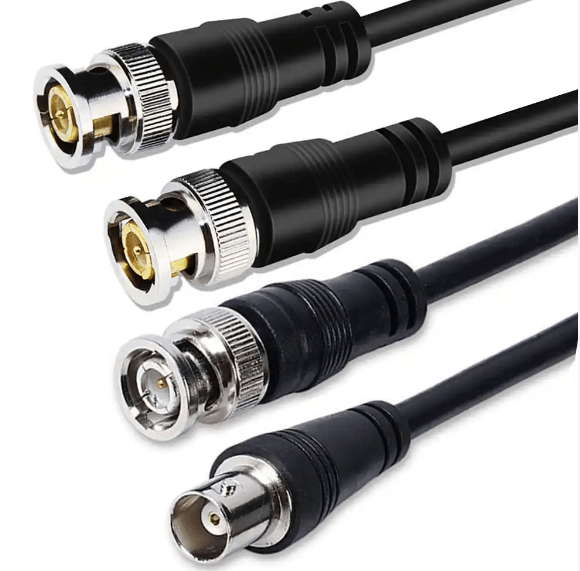
The BNC (Bayonet Neill-Concelman) interface is a cylindrical, bayonet-style connector designed for RF (radio frequency) and analog signal transmission. Developed in the 1940s by Paul Neill and Carl Concelman, it became a standard for decades in telecommunications, broadcasting, and test equipment. Key milestones:
- Design origin: Initially created for military radar systems during WWII, later adopted for commercial use.
- Core purpose: Enable secure, low-loss signal connections in coaxial cable setups, replacing screw-on connectors with a quicker bayonet locking mechanism.
II. Physical Structure and Key Components
- Mechanical Design:
- Bayonet Locking System: Three slots on the female connector align with lugs on the male plug, twisting 1/4 turn to lock (hence “bayonet” style), ensuring vibration-resistant connections.
- Coaxial Construction:
- Center Pin: Carries the signal (typically copper or gold-plated for conductivity).
- Dielectric Insulator: Separates the center pin from the outer shield (e.g., Teflon or polyethylene).
- Outer Conductive Shield: Blocks electromagnetic interference (EMI) and serves as ground.
- Shell: Metal casing (brass or stainless steel) for mechanical protection and EMI shielding.
- Dimensions:
- Standard BNC: ~12 mm in diameter, suitable for RG-58 or RG-62 coaxial cables.
- Mini-BNC (rare): Smaller variant, ~8 mm, used in some legacy video equipment.
III. Technical Specifications and Signal Capabilities
- Frequency Range:
- Effective up to 4 GHz (ideal for RF signals below 1 GHz), with low signal loss (<0.5 dB at 100 MHz).
- Impedance Matching:
- Common impedance: 50 Ω (for RF and data) or 75 Ω (for video and CCTV), critical for minimizing signal reflections.
- Data and Signal Types:
- RF Signals: Used in radio transmitters, antennas, and satellite receivers.
- Analog Video: Standard-definition video (SD-SDI), composite video (e.g., old CCTV cameras), or VGA (via BNC adapters).
- Digital Data: Early computer networks (e.g., 10BASE2 Ethernet, obsolete since 2000s), test equipment (oscilloscopes, signal generators).
IV. Application Scenarios and Industry Use
- Broadcasting and Television:
- Connecting cameras to switchers, or transmitters to antennas in analog TV stations.
- Legacy video production equipment (e.g., SDI cables for studio setups before HDMI/USB-C).
- Telecommunications:
- Base station antennas, microwave links, and early telephone network backhaul.
- Test and Measurement:
- Oscilloscopes, spectrum analyzers, and RF signal generators (e.g., Agilent/Keysight equipment).
- CCTV and Security Systems:
- Analog cameras connected to DVRs via 75 Ω BNC cables (still common in older installations).
- Military and Aerospace:
- Radar systems, avionics, and tactical communications due to ruggedness and EMI resistance.
V. Advantages and Limitations
- Advantages:
- Secure Locking: Bayonet mechanism prevents accidental disconnection, critical in vibration-prone environments (e.g., aircraft).
- Low Signal Loss: Coaxial design ensures minimal degradation for RF and video signals over short distances (up to 100 meters).
- Ruggedness: Metal construction withstands harsh conditions (temperature, moisture, physical stress).
- Limitations:
- Non-Hot-Pluggable: Connecting/disconnecting under power can damage the center pin or cause signal spikes.
- Limited Bandwidth for Modern Needs: Struggles with high-definition video (HD-SDI requires multiple BNC cables, vs. single HDMI/USB-C).
- Bulky and Heavy: Less suitable for portable devices compared to modern connectors (e.g., SMA for small RF modules).
- Complex Termination: Requires precise cable stripping and crimping, increasing installation time vs. plug-and-play options.
VI. Decline and Modern Alternatives
- Replacement Drivers:
- Digital Transition: HDMI, DisplayPort, and USB-C dominate in video due to higher bandwidth and ease of use.
- RF Innovations: SMA (SubMiniature version A) for smaller RF components, or fiber optics for long-haul signals.
- Ethernet Shift: 10BASE-T (RJ45) replaced 10BASE2 (BNC) in networking by the 1990s.
- Niche Survivals:
- Industrial Settings: Older factories, power plants, or military systems where upgrading is costly.
- Ham Radio and Hobbyists: Amateur radio enthusiasts still use BNC for antenna connections.
- Test Equipment: Some legacy oscilloscopes or signal analyzers retain BNC ports for compatibility.
VII. Modern Adaptations and Accessories
- Adapter Ecosystem:
- BNC to RCA (for composite video), BNC to HDMI (for the legacy video-to-digital conversion), or BNC to SMA (for RF equipment).
- High-Frequency Variants:
- 75 Ω BNC for Video: Optimized for CCTV and analog video, often with gold-plated contacts for durability.
- 50 Ω BNC for RF: Used in wireless test setups, such as measuring WiFi or cellular signal strength.
VIII. Conclusion
The BNC interface remains a testament to enduring engineering, thriving in specialized fields where reliability and EMI resistance outweigh modern conveniences. While its role has shrunk in consumer tech, its legacy persists in industrial, military, and RF applications. As digital standards evolve, BNC’s bayonet-locked design continues to serve as a robust solution for environments that prioritize signal integrity over miniaturization.


Leave a comment